|
I wont go here into the details of the schematics: it would require a complete book, and these schematics are the ownership of Dunlop Manufacturing Inc. Those who want to know more can read the patents registered by SR&D and will learn a lot there.
But it is possible to describe the guidelines that were followed by Tom Scholz and his team: the most interesting is to see how consistent the technology of SR&D was, from 1982 to 1994. As a matter of fact, the options and choices of the first Rockman were used till the end of SR&D's activities.
OpAmps
 |
The Rockman items are analog signal processors.
Analog signal processing consists in applying mathematical processes to a voltage that represents the signal (hence the term analog).
The best solution to handle mathematical processes is the Operational Amplifier (OpAmp), an Integrated Circuit (IC) created in the seventies for this specific purpose.
An OpAmp, taken alone, doesn't do much: basically, it can sump up, subtract or compare two voltages.
An OpAmp is a general usage component that allows building all the processes required for guitar signal (filters, gain stages, clipping, compression, etc
), provided you know how to combine it with the right passive components. SR&D, and other companies of course, has developped a huge know-how on the basis of these OpAmps.
Once you have made the choice to use OpAmps, there is no need for other active components such as discrete transistors, unless you have to reduce the manufacturing cost (and global quality): that's what people do when they build cheap stompboxes...
|
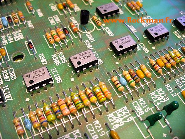
The first OpAmps were noisy: the old 741, for example, breathes like hell. A new generation of OpAmp was created in the late seventies: the TL071 (single), TL072 (dual) and the TL074 (quad). These OpAmps were silent, and still today, have excellent characteristics: enough anyway for guitar signal processing, which is not hifi. They are still manufactured today, and can be now purchased at almost no cost.
All the Rockman items are based on this OpAmp (TL072 and TL074). The design was optimized for this specific technology: replacing them by recent Burr Brown OpAmps can result in squealing and hiss problems. These new OpAmps have better characteristics that simply make the Rockman circuits unstable!
Since OpAmps are also an excellent component to build high quality buffers, they are used in all the Rockman items all along the audio path, from the first guitar input to the last stereo inputs. The input impedances are all really high (2Mohms) and the output impedances are low enough to match any other device without frequency response damage.
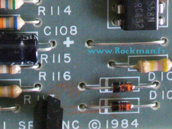
LEDs clipping
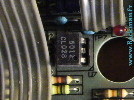
In the Rockman line, the OpAmps are not used to provide directly the clipping: they are always used in their linear range. The clipping components are a pair of LEDs (right picture - X100), and the OpAmps around them are used to filter the signal to obtain the proper sound, without clipping themselves (they are always used in their linear range).
Here's a very instructive extract of an interview given by Tom Scholz to Craig Anderton, for Guitar World in February 1990:
CA: What do you think about tubes? I would assume that the reliability aspect of tubes would make them less appealing to you.
TS: They are terrible. I used to use them on the road alot and would lose one every night. On the other hand, they distort a certain way, drive a speaker in a certain way, and through purely dumb luck, some people realized that driving them with the right kind of signal gave a neat sound. There weren't many people who could get a transistor overdrive to do the same thing. Actually, though, I dont use tubes or transistors as overdrive elements; I use LEDs. The bottomline the consumer really wants is something that sounds great. It doesnt matter if its tubes, transistors or LEDs, if you do the right thing with them. |
 |
 |
Enough said?
No, things would be too simple... SR&D used:
- Classic diodes in the Rockman I, II and IIB
- LED's in the X100
- Classic diodes in the Soloist (left picture)
- LED's in the Rockmodules and the XPR
- Both LED's and classic diodes in the Ultimatum Distortion Generator!
That's just an example of the complexity of SR&D's approach of gear design: these guys were continuously experimenting and improving their products, and it's sometimes really difficult to understand what the rationale was.
Unless the only rationale was to use your ears and chose what sounds best!
|
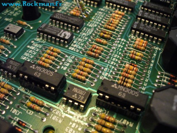
BBD's
The Brigade Bucket Devices (BBD) exist in their modern form since 1975. They are actually the only way to obtain a time delay with analog solid-state components: before digital gear became available, time-based effects were all based on electro-mechanical means (spring reverb, tape echo, oil can, etc
).
A BBD is composed of a series of capacitors, linked by electronic switches. These switches are controlled by a clock that allows pouring the contents of Bucket n into Bucket n+ 1. If you have N Buckets, and if the time interval between the clock pulses is T, the input signal is replicated at the output after a time interval equal to NxT.
In a BBD, the buckets are capacitors that can store the instant value of the input voltage. The first capacitor, coupled with the input switch, samples the input signal ate the clock rate. We say sampling. Does it mean that BBDs are digital components? No, because in a BBD, the signal is still a voltage, not a number stored as a series of 0 & 1. BBD's are analog components, based on an analog sampling technique
BBDs obey to Shannons theorem about sampling: the bandwidth cannot be wider than half the sampling rate. To get a good bandwith, but also a good signal-to-noise ratio (ie no loss in the high frequencies), you need a fast clock rate, hence a shorter delay. In other terms, a BBD echo cannot provide too long a delay, or the sound quality will rapidly be degraded.
|
 |
OK, lets put more buckets in the BBD, and well get longer echoes. Well, it works, within certain limits: the transmission from of capacitor to another is far from perfect, and you lose some details at every transmission. The clock-rate versus BBD elements compromise prevents getting correct echo units that go beyond this one second limit, in guitar applications. BBDs are great to build chorus and flangers, which require very short delays (less than 50ms). One can also build very simple reverb units. Not top rank studio reverbs (only digital can do that with electronics), but one can build a simple reverb effect: thats what you have in the Rockman headphone amps, and in the XP series.
We had to wait for the digital delay units to get clean, long echoes for the guitar at an affordable budget: that was the mid-eighties. So one could wonder why Scholz didnt use digital technology to build the Rockman Stereo Echo
There are several answers.
First, there was no need for it: the objective was to build a device that sounds good, not to build the longest possible delay unit. BBDs do that perfectly, and the Rockman Stereo Echo is an awesome device, still 20 years later. For a guitarist, a good echo sound is warm, and tape echoes provide this warm sound resulting from natural tape dynamics and from their bandwidth. This subtle compression and this bandwidth limitation are easy to reproduce with BBDs, and thats actually what one gets with the Rockman Stereo Echo.
Second, designing a digital echo unit requires different skills. This was especially true in the eighties. SR&D was an electronic company, not a software company. Hiring software engineers for one product would have been complex and contradictory. It is possible, in 2007, to include a dedicated digital chip in an analog device: this digital chip having its own D/A and A/D converters, you can use it like an analog component. But it was not possible twenty years ago.
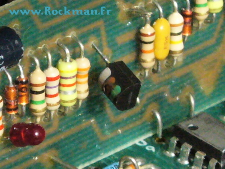
J-FETs and Optocouplers
OpAmps are strictly linear, and Rockman's clipping is made by LEDs (or diodes...). But other active components were necessary to build some non-linear gain stages: the compressors and the AutoClean.
The compressors (a critical element of the Rockman sound) are all based on the same scheme: an OpAmp with a feedback loop that controls the gain via a J-FET. This very simple circuit was adapted to match the guitar signal, and the adaptations were not obvious: they consist controlling as the same time the frequency response and the time constants (attack and release) with a smart network of capacitors and diodes.
J-FETs are also used in the Smart-Gate, one of the best noise suppression circuits, still today: a first FET is used to close the low-pass filter that actually suppresses the noise when desired, and a second FET is used to control the way the gate closes proportionally to the signal decay without ever cutting the end of the notes.
|
 |
SR&D could certainly have used optocouplers instead of FETs, but it would have been more expensive for the same result. Optocouplers are used in one specific case: the complex Autoclean circuit that allows controlling the distortion rate from the guitar pot, without loss of volume, nor tone response alteration. The Autoclean certainly gave a hard time to Tom Scholz, if we compare the first release, in the Sustainor 100, and the last ones, in recent Sustainor 200s and Distortion Generators. The most recent items have an Autoclean that really works great, while the first ones are far from perfection.
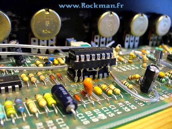
FET switches
SR&D made an extensive use of the 4053 and 4066 ICs. These chips contain several FET switches that are used every time silent and transparent switches were necessary, to include the bypass systems. Its an efficient, smart and cost-effective solution, based on standard components that are still available today.
The Double-IC modification, in the sought-after late Sustainors, consists in adding one more switch in the compressors circuit to shorten the release time. Since there was no room left on the PCB for one more switch, SR&D simply soldered one extra 4066 IC on the top of a first one: thats the piggy-back mod
This "piggy-back" technique was used not nly in the Sustainor, but in the half-rack Smart Gate too, and the Rockman A12-50 combo, as shown here.
Discrete FETs were used here and there as switches, when voltages were too high for the 4053 and the 4066. The Instrument EQ has a +/-12V voltage supply, while the other modules were powered by +/-8V only. SR&D has used discrete FETs for the bypass system in the EQ, and made the same choice for the two stompboxes, the AGP and the UDG.
|
 |
Balanced power supply
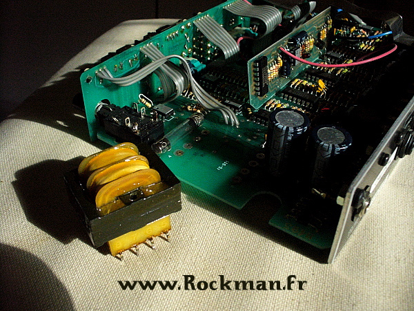
| The OpAmps are components that require two voltages to operate: this is consistent with the fact that the audio signals are handled as an alternative voltage, with positive and negative halves. The two power supply voltages are thus two opposite DC voltages, +V and V, with respect to the reference zero voltage: the ground. Thats a total of three connection terminals.
In the common stompbox format gear, there is one voltage only: usually +9V. To allow the circuit handling the alternative signal and its negative halves, it is necessary to bias the circuit with an additional voltage, usually half of the main DC power supply voltage (i.e. 4.5V in a pedal). This technique works fine if the design is made carefully, but its not the best way to build professional gear:
- Instead of referring to the stable zero voltage of the ground, the signal refers to the floating bias voltage.
- When a circuit is powered by 9V, its headroom is only half of what a symmetrical +/-9V power supply allows. Its not critical with the weak guitar level signals, but if you want to operate at the stronger line signal levels to get a much better signal to noise ratio, it can become tricky.
- Symmetrical power supplies allow noise cancellation, a bit like a humbucker guitar pick-up or a balanced audio cord: the residual hums of the DC voltages are cancelled instead of being added to the audio signal (symmetrical power supply is also called balanced power supply).
|
All in all, even if its perfectly possible to design a correct circuit with the bias technique and one power supply voltage only, balanced power supply is preferred for professional grade audio gear, and unbalanced power-supply is used only when manufacturing cost is an issue.
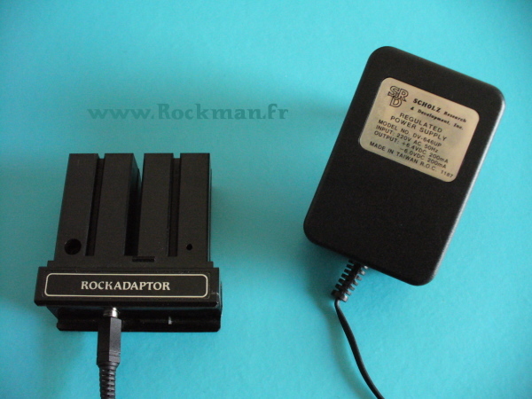
Thats how the Rockman headphone amps needed a total of eight 1.5V batteries, four batteries providing +6V on one side, and the four others providing -6V on the other side. In the Ace economic series, the balanced power supply was replaced by a cheaper 9V unbalanced power supply
A balanced voltage requires three connections instead of two only with an unbalanced power supply. The first Rockman headphone amps (between 1982 and 1986) had in fact no connector for an external wall-wart. SR&D had created a specific adaptor, the Rockadaptor, which allowed connecting three points directly inside the batteries compartment.
In 1986, this Rockadaptor principle was, more logically, replaced by a mini TRS jack, placed on the side of the X100, Soloist and Bass Rockman.
As for the Rockmodules, they were directly equipped with their own built-in transformer and regulated balanced power supply, at least for the US/Canada 110V versions.
Wall-warts and export versions
Wall-warts have always been available for the headphone amps.
I own three types of these specific +6.3V/-6.0V power supplies:
- 110V with Rockadaptor (the regulation circuit being inside the Rockadaptor), from 1982 to 1986
- 110V with TRS mini-jack (the regulation circuit being inside the wall-wart), since 1986. An empty Rockadaptor was then issued, also with a mini-jack.
- 220V with TRS mini-jack, probably since 1986.
I have never seen any 220V version of the Rockadaptor early version of these power supplies, and do not know if European users were obliged to play with batteries or if there was actually a 220V Rockadaptor before 1986.
Wall-warts were also used for the export versions of the Rockmodules. In the US/Canada zone, i.e. 90% of SR&Ds market, the mains voltage is 110VAC, and the mains plugs have a given shape and format.
Japan has 100VAC and US type plugs: the US Rockmodules can be used in Japan (the 60Hz frequency is not an issue on these analog devices).
|
|
In the other countries - the export market for SR&D - the mains voltage is 220 or 230VAC, and the plugs are not normalized. It was therefore more logical for SR&D to export the Rockmodules without the built-in transformer, the regulation circuit being left as is. This allowed having different wallwart shapes at the local level: UK, France, Italy, Germany, etc
SR&D had just a small modification to do in the power supply wiring to allow all the modules operate with the same 12VAC voltage, the connector being a classical barrel plug.
Two exceptions, though: for the Guitar Compressor and the Smart Gate, SR&D has produced 220VAC versions, sold without plug at the end of the cord. Why not.
The bigger products such as the XPR, XP100, PGE2, and the Midipedal were produced both in 110V and 220V versions: I own one of each, and had nothing to do to use them in France.
As far as I know, the A12-50 and the XP212 combos were not sold in Europe: I have bought one of the two A12-50s that were actually shipped to a sub-contractor in Scotland by Jim Dunlop after he purchased SR&D: they are certainly the two only Rockman combos here, and are 110V models.
|